Particle analyses in an accredited testing laboratory
Increase your product quality by optimising production processes with the help of technical cleanliness. Gläser CleanTec is your competent partner for this.
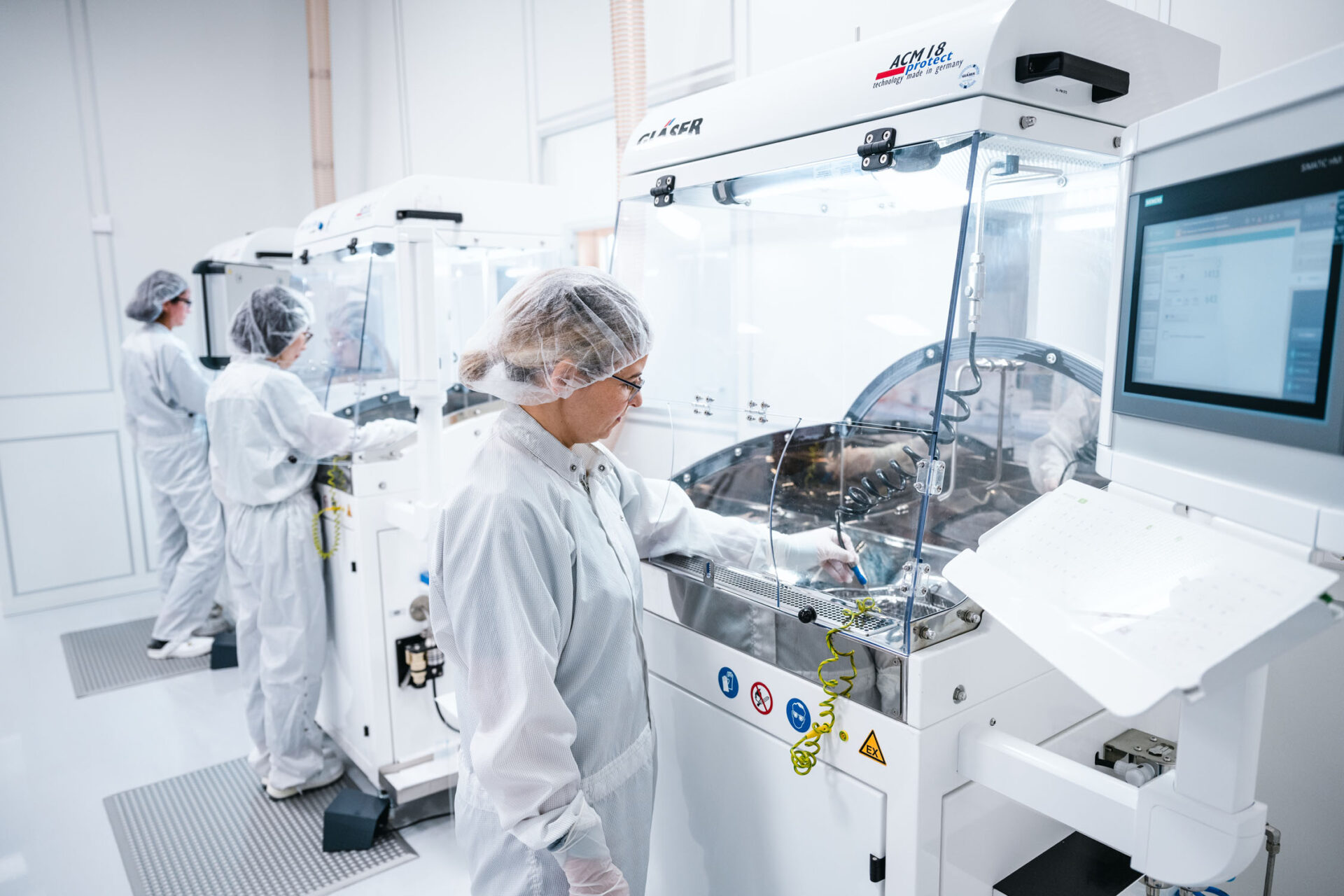
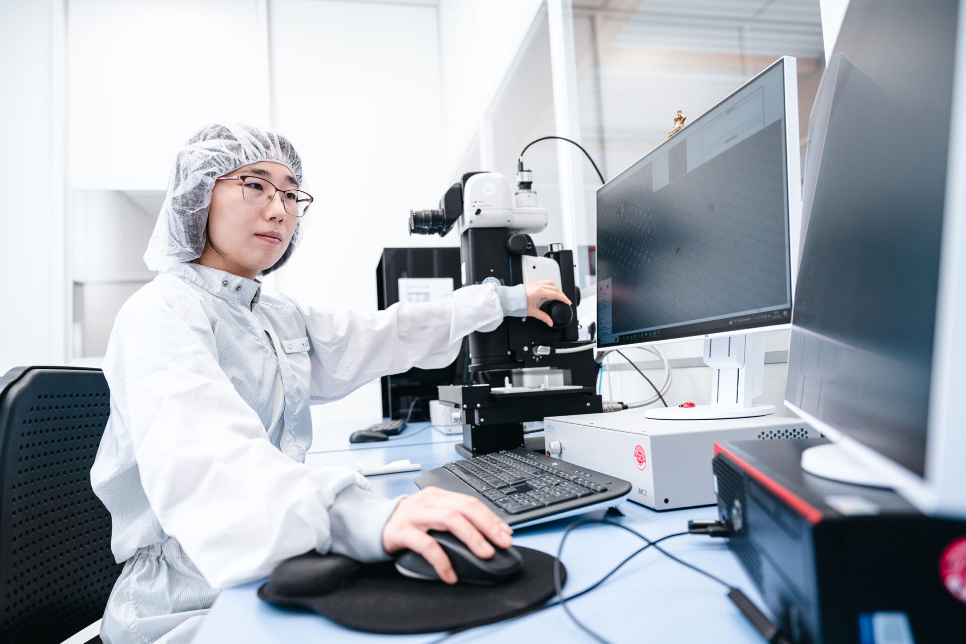
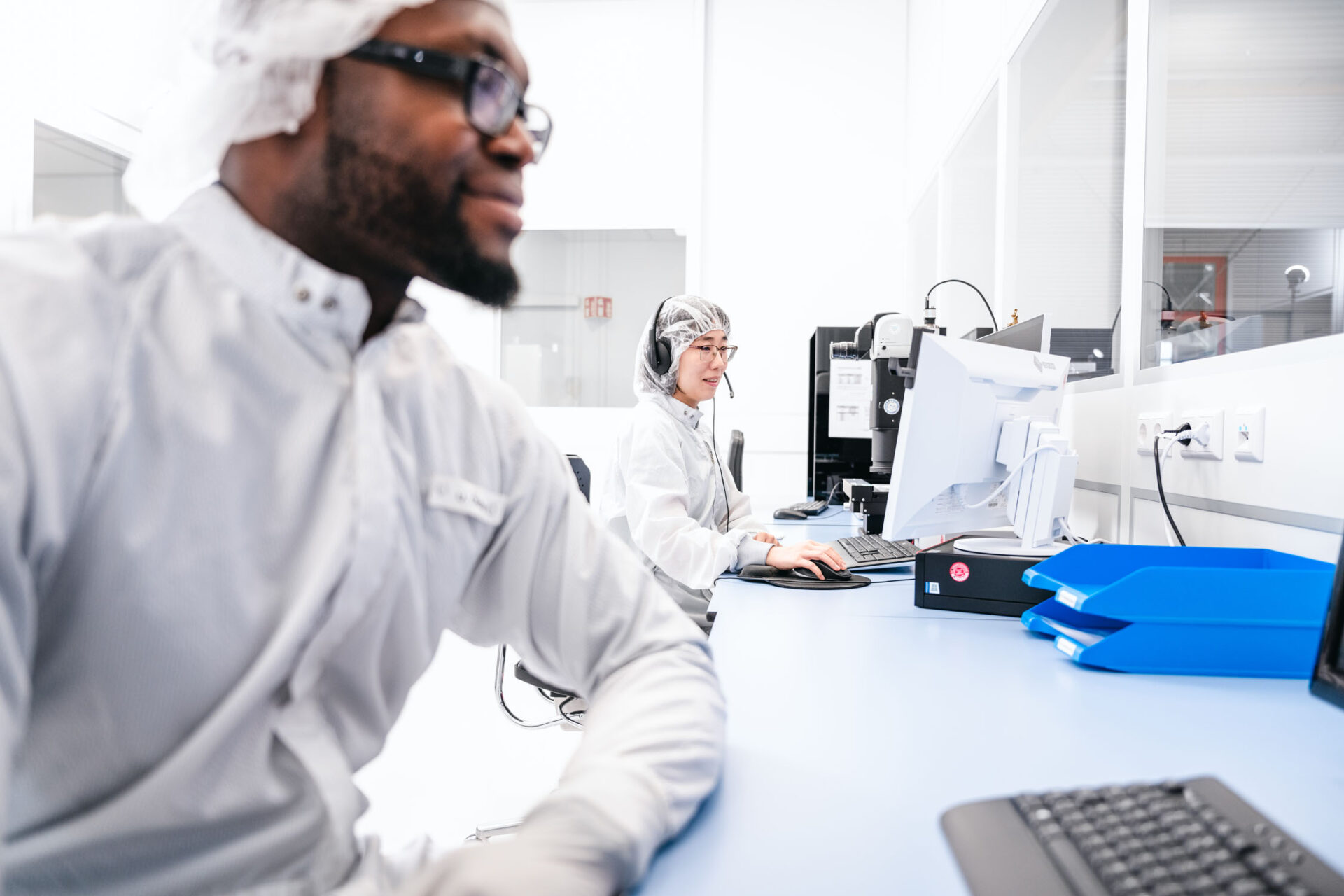
With state-of-the-art laboratory equipment, our highly trained laboratory team analyses your components for particulate and chemical-film contamination in our in-house ISO17025-accredited ISO class 7 cleanroom. Whether large or small, we can meet your individual requirements and carry out particle extractions on the smallest components in the mg range up to large parts with a total weight of up to 350 kg.
Our Services
Cleanliness analyses / residual dirt analyses
Determination of the particulate contamination of your components
Material analyses of your particles
Further analyses to determine the origin and damage potential of the particles
Chemical-filmic analyses
Determination of organic, ionic, and chemical contamination on components
Fluid / oil analyses
Determination of particulate contamination in fluids or oils according to ISO 4406/ISO 4407
Particle monitoring
Determination of the particulate load in the environment and on surfaces
Q&A
A technical cleanliness inspection refers to the process of evaluating and assessing, for example, a component’s cleanliness.
The result of such an inspection provides information on the remaining type, quantity, and size of contaminant particles after the component has been removed (usually after the final cleaning process).
A technical cleanliness inspection typically includes several steps:
– Analysis of requirements (specifications against which the component is to be tested)
– Sampling, usually after the cleaning process, i.e., in the condition in which the component is to be further used
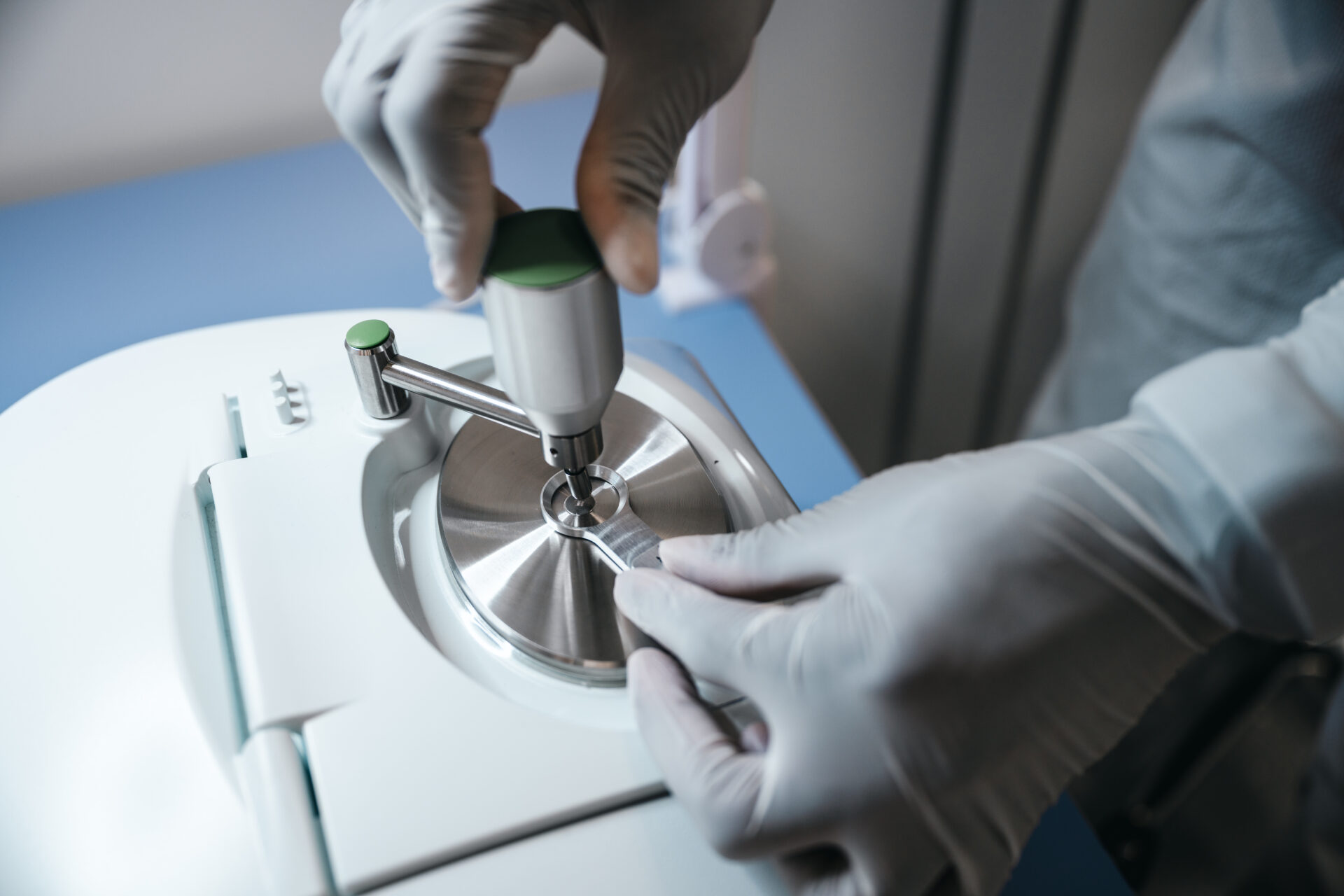
– Extraction of particles from the component, meaning detaching the particles from the component and capturing them using an analysis filter
– Analysis of the analysis filter using a light microscope to measure, count, and differentiate particles into metallic, non-metallic, and fibers
– Evaluation of the results compared to defined cleanliness standards/specifications
– Documentation of results and, if necessary, implementation of measures to improve cleanliness
First, it is necessary to determine which surfaces/partial areas of the component need to be tested (cm²).
It may be necessary to mask certain areas during the inspection.
If the entire component needs to be inspected, the following applies:
– A sufficient number of components must be tested simultaneously to cover a total surface area of 200 cm².
– For a component with a surface area of 20 cm², a total of 10 components need to be provided for this inspection.
– Additionally, it should be clarified whether a decay measurement for this component has already been conducted; otherwise, the number of components required will increase rapidly.
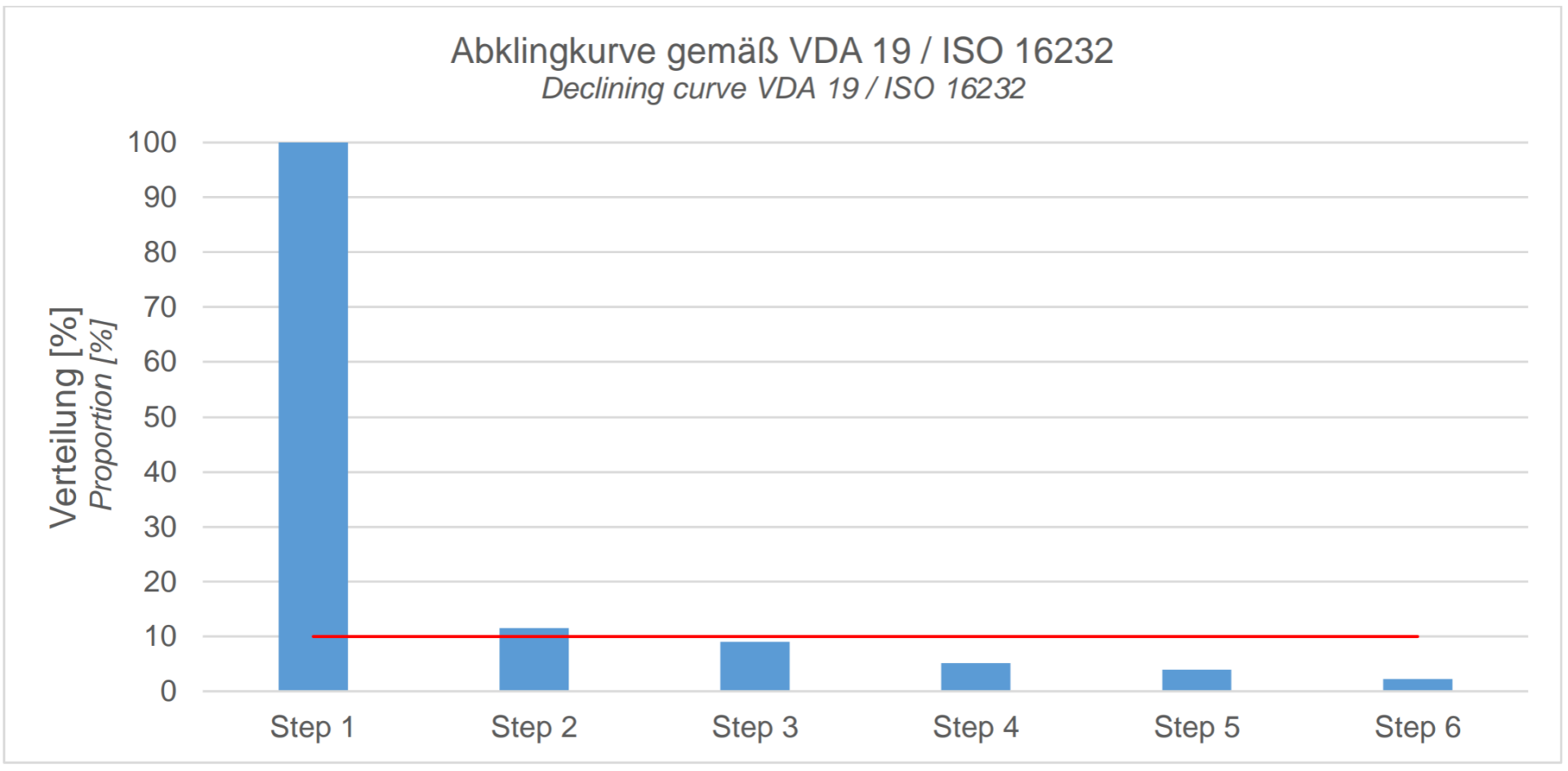
The decay curve, or qualification examination, is used for the final development of the extraction procedure (routine sampling/standard analysis).
The effectiveness of the extraction method determines whether the cleanliness of the component can be accurately assessed.
Therefore, during a cleanliness inspection, it must be demonstrated that soluble contaminant particles are extracted as completely as possible from the test component.
Since there is no absolute method for determining the actual particle load, decay measurements are performed.
Through repeated sampling of the component, it is determined whether the extracted particle load decreases, thus confirming that a suitable extraction method is in place.
The completeness of the extracted contaminants is determined by the so-called decay criterion.
The point of the decay curve is determined when the last extracted cleanliness value is less than 10% of the total amount of contaminants extracted so far.
This point is used to develop the routine sampling procedure.
Procedure:
– Define a presumably suitable test lot size
– Clean test equipment and perform blank value measurement
– Apply the extraction procedure with starting parameters 6 times consecutively
– After each extraction step, rinse the test equipment
– Calculation of the ratio between the cleanliness value and the sum of all extraction steps performed
– Upon reaching the decay criterion, develop the routine sampling procedure
– If the criterion is not reached, adjust the extraction parameters and repeat with a new component
A double check is applied when:- The extraction parameters need to be tested for their effectiveness
– The decay measurement and the parameters determined through it need to be confirmed by a double check
– The component deviates minimally from another component, and the results of the decay measurement of the first component need to be verified
In a double check, the component is tested twice on an as-yet-untested test lot, and cleanliness values are determined.
If the second cleanliness value is less than or equal to 30% of the sum of the two cleanliness values, the developed routine sampling conditions are suitable.
These can then be documented as test specifications.
Thus, a double check can potentially save time and money but often serves as additional assurance of the established routine sampling parameters.
Before any standard sampling, qualification examination, or double check, it must be demonstrated that only particles from the test component are included in the analysis result.
This means the blank value is conducted BEFORE the actual extraction of a test component and proves that all non-component particles (foreign particles) are as well excluded as possible and do not lead to false interpretations of the cleanliness state of the test component.
Sources of foreign particles can include:
– Test fluids and rinsing liquids
– Extraction equipment (baths, tanks, pipelines, valves, etc.)
– Handling during sampling and analysis
– Environment and personnel
– Any items that come into contact with the component and test fluid
The permissible blank value is calculated based on the cleanliness values of the component and must not exceed 10% of the required/anticipated cleanliness value of the component.
To achieve this as efficiently as possible, the selection of the right extraction equipment is crucial.
This topic is not exhaustively explained here but provides a basic overview of the term definition.
Exceeding the required particle limits can have many, nearly countless causes:
– Environmental conditions/rooms
– Ventilation technology/air conditioning/heating/ventilation systems
– Work clothing
– Cleaning concepts or weaknesses within them
– Handling by inadequately trained personnel
– Washing processes before packaging components
– Packaging itself
– Logistics
– …
Often, it is a combination of several of these factors that leads to exceeding the limits.
In such cases, it is essential to ensure through repeated tests whether this exceedance occurs with other components as well.
If this is the case, an external service laboratory can be consulted to perform the same sampling and compare the results with yours.
If the limits are still exceeded, you can do the following:
– Engage an external service provider to evaluate your production according to VDA19.1/ISO16232 & VDA19.2 recommendations
– In a workshop, work with your team to identify possible influencing factors and assess the situation
– Subsequently, the environmental situation will be evaluated using particle traps (monitoring) and a plant inspection from goods receipt to goods dispatch by experts in technical cleanliness
– Through interviews with your production personnel, photos of identified weaknesses, and a comprehensive audit catalog, you will receive detailed information about the weaknesses in your production, as well as an action list and recommendations for addressing these weaknesses
– It is also advisable to have ongoing support in achieving the limitsExperience shows that such support is not only helpful but necessary.
The extent of external consulting depends on the complexity of the task.
Sometimes, a few online appointments suffice, while in other cases, a thorough and on-site consultation is necessary to effectively and permanently master the challenges.
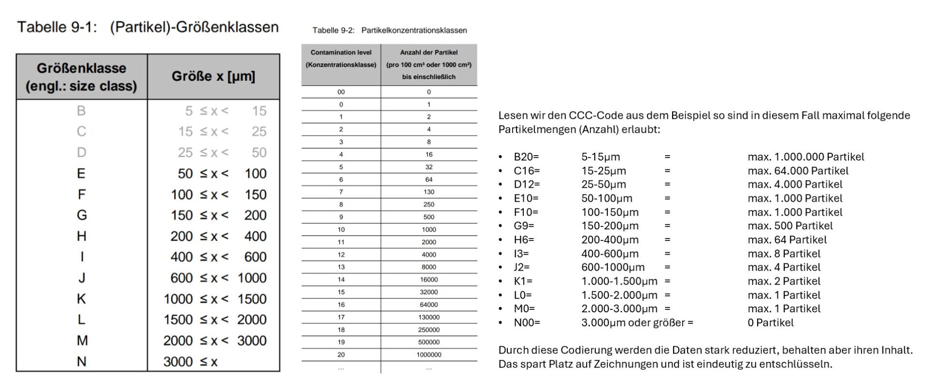
The CCC (Component Cleanliness Code ) is intended to shorten the specification of cleanliness values and is often indicated on drawings of components or in specifications. This coding was developed based on ISO16232-2007 and can only be applied to the particle size distribution.
It does not explicitly regulate individual particle types (fibres, shiny metallic) and the particle width is also not regulated.
During coding, the number of particles is assigned to a concentration class (contamination level).
Example: CCC = A(B20/C16/D12/E10/F10/G9/H6/I3/J2/K1/L0/M0/N00)) (Three reference values: A= per 1000cm², V= per 100cm³ and N= per component)
The number of particles is coded for A and V, but not for N.
The following tables are required to decode this code unambiguously. These can be found in VDA19.1 Chapter 9
Cleanliness Analyses / Residual Contamination Analyses
Extraction Methods
- Rinsing
- Spraying
- Dissolving
- Ultrasound
- Blowing
- Flowing
Available Test Media
- Cold Cleaner (hydrocarbon-based)
- Deionized Water
- Air (processed and filtered)
Particle Information
- Metallic shiny
- Non-metallic shiny
- Fibers
Possible Component Dimensions for Analysis
- Small components in the mm range
- Medium components up to 50 kg
- Large components up to 350 kg and max. 2 m in length
Analysis Methods
Microscopy
Automated light microscopic analysis of particulate contamination on components after extraction on a filter membrane. Classification of metallic and non-metallic shiny particles and fibres according to VDA 19.1 / ISO 16232 or according to individual customer requirements.
SEM-EDX
Material analysis of your metallic, mineral and abrasive particles. By precisely analysing the material, we determine the potential conductivity and hardness of the particles in order to assess their damage potential. The analysis also allows conclusions to be drawn about the origin of the particles so that you can specifically eliminate the cause of the contamination.
FTIR
Organic particles are analyzed not only for their size but also for their spectrum. By knowing the spectrum, the potential for damage can be assessed. Furthermore, conclusions can be drawn about the particle’s origin, which helps to target the source of contamination.
Surface Tension
Determination of surface tension using test inks in the range of 32 – 44 mN/m according to DIN 53364 or ISO 8296. The determined surface quality provides information on whether the surface is suitable for subsequent processes, such as bonding or welding. The result serves as a measure of the current condition of your component.
Gravimetry
Quantitative statement about the total mass of the extracted particle load = Residue weight the particle load extracted from the component is determined using a 5-digit analytical balance by drying and weighing the analytical filter before and after filtration of the analysed liquid.
Particle Analysis Using SEM/EDX
Determination of the material of metallic and mineral particles
Metallic and mineral particles are identified not only for their size but also for their elemental composition. By knowing the composition, the hardness and conductivity of the particles can be assessed, and their damage potential can be determined. Additionally, it is possible to draw conclusions about the particle’s origin and thus target the source of contamination.
Examples of hard (abrasive) particles:
- Sand, Corundum, Silicates, Oxides and Mineral ceramics
- Material classes and compositions of metallic and mineral particles
- Correlative material analysis of individual particles that have exceeded the threshold
- Material analysis of all particles on the filter membrane from 5 µm possible
- Determination of the damage potential of particles: hardness, conductivity, and magnetism
Advantage: Determining the damage potential and information on the origin of the particles
Particle Analysis Using FTIR Analysis
Determination of the material of organic particles (plastic, wood, cardboard, etc.)
- Organic particles can be identified using infrared spectroscopy (IR)
- The measured IR spectrum is matched with a database of typical materials to determine the particle material
- The measured spectrum can be compared with reference materials, allowing conclusions about the origin of organic contaminants (e.g., plastics, packaging contaminants, textile fibers)
- IR analysis involves preparing the particle on the ATR crystal of the FTIR microscope
- The result includes the particle image, the IR spectrum with reference spectrum, and the definition of the organic material
Advantage: Determining the damage potential and information on the origin of the particles
Chemical-Film Contamination Analysis
Determination of organic, ionic, and chemical contaminants on components
In addition to particles and fibers, filmic contaminants such as residues from coolants and lubricants are sources of organic contamination on your component, which can quickly lead to disruptions in further manufacturing processes. Various analysis methods provide detailed information about the type of organic contamination and allow you to target its source effectively.
Examples include:
- Coatings
- Paint residues
- Preservatives and adhesives
- Greases (e.g., coolants and lubricants, fingerprints)
- Organic particles and fibers
Emission Measurement ¹ ²
Emission measurement of components using GC/MS
For the determination of volatile components in your parts, we offer analysis using a gas chromatograph with mass spectrometer. Small component sizes (45 mm x 30 mm), medium sizes (245 mm x 265 mm), and large sizes (555 mm x 870 mm) can be analyzed. Additionally, depending on the application environment of your component, the analysis can also be conducted at higher temperatures up to 300 °C. The measurement is performed according to VDI 2083 Sheet 17 and in accordance with ISO 12219-3.
Ion Chromatography ¹ ²
Analysis of ionic contamination on component surfaces
If you need quantitative and qualitative information on contamination of your assemblies to assess surface quality, ion chromatography (IC) is the right choice. After extracting the contaminants with ultrapure water (according to SEMI F57 / IPC-TM-650 23.28.2), the ultrapure water is analyzed for cations (according to ISO 14911) or anions (according to ISO 10304-1).
ROSE Test ¹ ²
ROSE Test (ionic contamination measurement)
The ROSE Test quantitatively measures ionic contamination on your electronic assembly, which can result from soldering and galvanic processes. For components such as circuit boards, ionic contamination is often the cause of serious functional failures. After extracting the surface contamination, conductivity is measured based on IPC-TM-650 2.3.25. The result is given in NaCl equivalents. Based on the result, you can check whether the specifications for maximum allowable ionic contamination are met.
Gravimetry ¹ ²
Gravimetric NVR Determination – Test for non-volatile residues
Based on ISO 759, non-volatile residues (NVR) on your component surface are separated by solvent extraction and gravimetrically analyzed after solvent evaporation. This analysis provides a quantitative determination of non-volatile components, which can significantly impact the quality and performance of your product. This test is especially important in electronics or medical device manufacturing, as well as in the chemical and pharmaceutical industries.
TOC Measurement¹ ²
TOC Analysis
Total Organic Carbon (TOC) analysis indicates the sum of all organic carbon on the surface of your component and is a measure of its organic contamination. This involves extracting residues with ultrapure water and then analyzing the extract. This test is particularly important for verifying the cleaning quality of medical devices.
1 These analyses are not within the scope of our accreditation.
2 These analyses are carried out in an external partner laboratory.
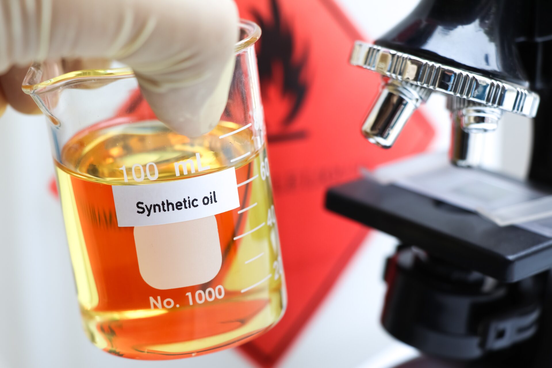
Liquid/Oil Analyses
Determination of particulate impurities in liquids or oils
according to ISO 4406/ISO 4407 or customer specifications.
Determination of the purity class by means of filtration of the sample liquid. The particles are retained by a membrane and then analysed under a microscope. Automatic particle counting in accordance with ISO 4406/ISO 4407 or customer specifications.
During microscopy, the metallic and non-metallic particles, including fibres, are particles, including fibres, are recorded and images of the largest particles are added to the report.
Your advantages at a glance:
- Checking the wash water of cleaning machines for particulate contamination.
- Analysing oils to determine the cleanliness classes.
- Monitoring of a wide range of process aids (liquids)
Particle Monitoring
The Particle Trap for Periodic Observation
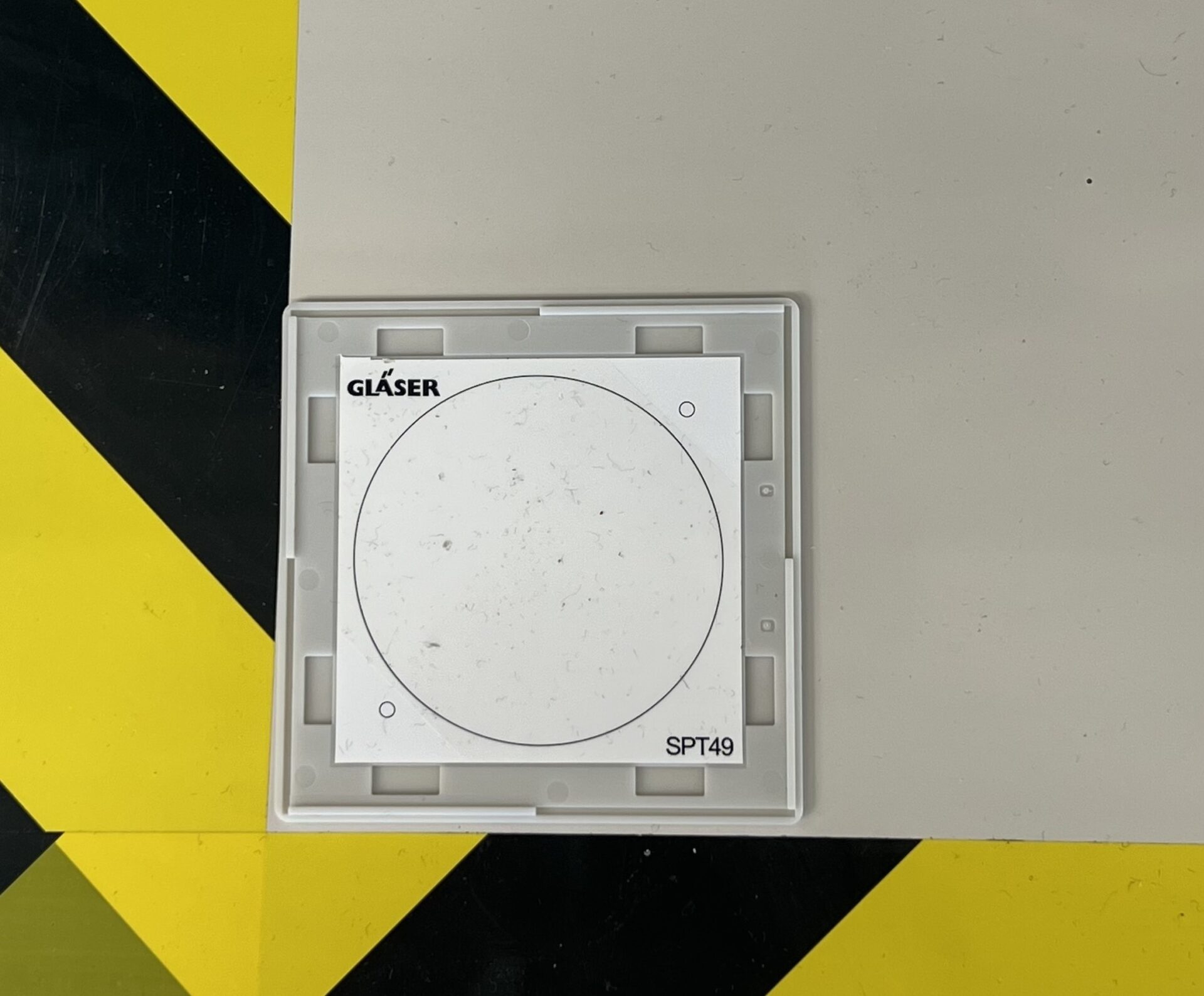
Do you want to find out if there is a source of contamination in your immediate production environment? Or do you already know that your production is affected by contamination but can’t identify the source? Simply lay out one of our GLÄSER particle traps for a certain period of time to find out exactly this. Particle traps are used to assess and identify environmental contamination.
This contamination can result from internal transport routes, open entrances and windows, or particle deposition due to abrasion. Contaminants settle on the adhesive pad of the particle trap and can then be subjected to microscopic examination. Send the particle trap to our laboratory, and we will count and measure the particles.
The Particle Stamp for a Snapshot
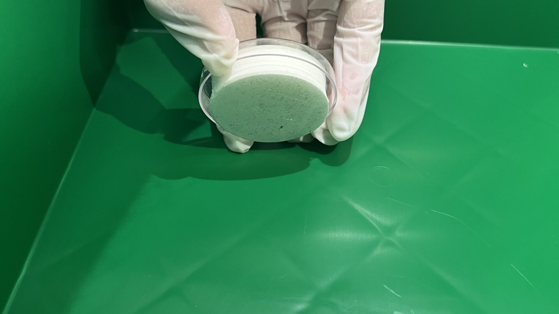
In contrast to the particle trap, the particle stamp is used to assess and determine surface contamination. With the stamp, you can easily stamp the desired area and obtain a snapshot of your contamination at a specific location. Accurate results are obtained through microscopic analysis of the stamp in our laboratory.
With these concrete results, you can then take targeted measures to address the contamination. Your production process is now cleaner!
The information sheet with further details on the use of the particle trap and stamp can be conveniently found under Downloads.
Our virtual laboratory
Visiting hours: 24/7
Visit us in our virtual laboratory – whenever you want. Explore our testing machines, developed in-house. Discover what modern laboratory equipment looks like today. Gläser CleanTec is a world leader in Technical Cleanliness in the fields of: mechanical engineering, laboratory analytics, training, consulting, service, and trade.
